Lecroy Lt262 /350M Осциллограф Lecroy
Offer ID: 573970913000
Статистика продавца
Свойства товара
Описание товара
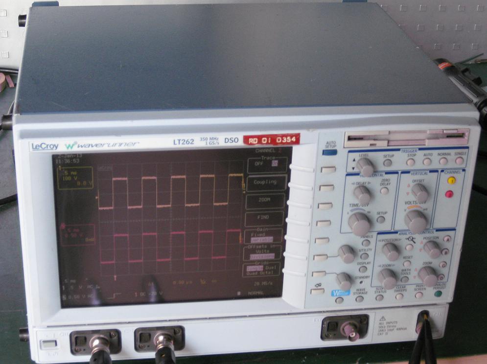
特价供应二手LeCroy LT262 Digital Oscilloscope /350M力科示波器
LeCroy LT262 Digital Oscilloscope
LeCroy Waverunner-2..........
Specifications
Vertical System LT264 /M LT262
Input Channels 4 2
Analog Bandwidth @ 50 Ohms (-3 dB) 350 MHz 350 MHz
Hardware Bandwidth Limits 20 MHz, 200 MHz
Input Impedance 50 Ohms ± 1%; 10 MOhms / 12 pF typical (using PP006 probe)
Input Coupling 1 MOhms : AC, DC, GND; 50 Ohms : DC, GND
Maximum Input 50 Ohms : 5 Vrms; 1 MOhms : 400 Vmax (peak AC <=5 kHz + DC)
Vertical Resolution 8 bits; up to 11 bits with enhanced resolution (ERES)
Sensitivity (50 ohm or 1 M ohm) 2 mV - 10V/div fully variable
DC Gain Accuracy ± (1.5% + 0.5% of full scale)
Offset Accuracy (50 ohm or 1 M ohm) ± (1.5% + 0.5% of full scale + 1 mV)
Offset Range 2 mV 99 mV/div: ± 1 mV
100 mV 99 mV/div: ± 10 V
1V ? 10 V/div: ±100 V
Isolation Channel-to-Channel > 250:1 at same V/div settings
--------------------------------------------------------------------------------
Timebase System
Timebases Main and up to four independent zoom traces simultaneously
Ranges 500 ps/div ? 1000 s/div 1 ns/div ? 1000 s/div
Clock Accuracy <=10 ppm
Interpolator Resolution 5 ps
External Clock Frequency 500 MHz maximum, 50 Ohms, or 1 MOhms impedance
Roll Mode ? Operating Range time/div 500 ms 1000 s/div or sample rate < 100 kS/s max
External Timebase Clock 500 MHz maximum external sample clock input on front panel EXT BNC
Acquisition System
Single-Shot Sample Rate
1 Channel Max. 4 GS/s 4 GS/s 1 GS/s 1 GS/s
2 Channels Max. 4 GS/s 2 GS/s 1 GS/s 1 GS/s
3 4 Channels Max. 2 GS/s NA 1 GS/s NA
Maximum Acquisition Points/Ch
1 Channel Max. 500k / 2M / 8M 500k 100k / 1 M 100k
2 Channel Max. 500k / 2M / 8M 250k 100k / 1 M 100k
3 - 4 Channel Max. 250k / 1M / 4M NA 100k / 1 M NA
Acquisition Modes
Random Interleaved Sampling (RIS) 50 GS/s for repetitive signals: 200 ps/div ? 1 μs/div
Single-Shot For transient and repetitive signals: 1 ns/div ? 1000 s/div
Sequence
LT262 / 264 2 400 segments
LT372 / 374 2 1000 segments
Memory Option M or L 2 ? 400 segments
Intersegment Time 50 μsec max.
Acquisition Processing
Averaging
Summed averaging to 10 sweeps; continuous averaging with weighting range from 1:1 to 1:1023 (standard).
Summoned averaging up to 10 6 sweeps (optional with WAVA)
Enhanced Resolution (ERES) From 8.5 to 11 bits vertical resolution
Envelope (Extrema) Envelope, floor, roof for up to 10 6 sweeps
Triggering System
Modes Normal, Auto, Single, and Stop
Sources
Any input channel, external, Ext/10 or line; slope, level, and coupling unique to each source (except line trigger)
Inactive channels usable as trigger inputs.
Slope Positive, Negative, Window
Coupling modes DC, AC, HF, HFREJ, LFREJ
AC Cutoff Frequency 7.5 Hz Typical
HFREJ, LFREJ 50 kHz typical
Pre-trigger delay 0 100% of horizontal time scale
Post-trigger delay 0 10000 divisions
Hold-off by time or events
Up to 20s or from 1 to 99 999 999 events
Internal trigger range ±5 div
Max trigger frequency 500 MHz (350 MHz on LT264, LT262)
External trigger input range ±0.5 ( ±2.5 V with Ext/5 selected )
Maximum ext. input @ 50 Ohms ±5 V DC or 5Vrms
Maximum ext. input @ 1 MOhms 400 Vmax ( DC + peak AC < 5 kHz )
Automatic setup
Auto Setup Automatically sets timebase, trigger, and sensitivity to display a wide range of repetitive signals
Vertical Find Automatically sets the vertical sensitivity and offset for the selected channels to display a waveform with maximum dynamic range
Probes
Model PP0056 10 : 1, 10 MOhms with auto-detect (one per channel)
Probe System: Probus? Automatically detects and supports a wide variety of differential amplifiers; active, high-voltage, current, and differential probes
Scale Factors Up to 12 automatically or manually selected
Color Waveform Display
Type VGA color 8.4" flat-panel TFT-LCD
Resolution VGA 640 x 480 pixels
Screen Saver Display blanks after 10 minutes (when screen saver is ?on?)
Real Time Clock Date, hours, minutes, and seconds displayed with waveform
Number of Traces Display a maximum of eight traces. Simultaneously display channel, zoom, memory, and math traces.
Grid Styles Single, Dual, Quad, Octal, XY, Single + XY, Dual + XY; Full Screen gives enlarged view of each style.
Intensity Controls Separate intensity control for grids and waveforms
Waveform Styles Sample dots joined or dots only ? regular or bold sample point highlighting.
Trace Overlap Display Select opaque or transparent mode with automatic waveform overlap management.
Analog Persistence Display
Analog & Color-Graded Persistence Variable saturation levels; stores each trace?s persistence data in memory.
Trace Selection Activate Analog Persistence on a selected trace, top 2 traces, or all traces.
Persistence Aging Time Select from 500 ms to infinity.
Trace Display Opaque or transparent overlap
Sweeps Displayed All accumulated or all accumulated with last trace highlighted
Zoom Expansion Traces
Display up to Four Zoom Traces
Vertical zoom up to 5X expansion, 50X with averaging
Horizontal zoom expand to 2 pts/div, magnify to 50000X
Auto Scroll automatically scans and displays any zoom or math trace.
Rapid Signal Processing
Processor PowerPC
Processing Memory Up to 128 Mbytes
Realtime Clock Dates, hours, minutes, seconds and time stamp trigger time to 1 ns resolution
Internal Waveform Memory
Waveform M1, M2, M3, M4 (Store full-length waveforms with 16 bits/data point)
Zoom and Math Four traces A, B, C, D with chained trace capability
Setup Storage
Front Panel and Instrument Status Four non-volatile memories and floppy drive are standard. Hard drive and memory card are optional.
Interface
Remote Control Full control of all front panel controls and internal functions via RS232C, GPIB, or Ethernet
RS-232-C Asynchronous transfer rate of up to 115.2 kbaud
GPIB Port Full control via IEEE ? 4888.2; configurable as talker/listener for computer control and data transfer
Ethernet (optional) 10 BaseT Ethernet interface
Floppy Drive Internal, DOS-format, 3.5" high-density
PC Card Slot (optional) Supports memory and hard drive cards
External Monitor Port Standard 15-pin D-Type VGA-compatible
Centronics Port Parallel printer interface
Internal Graphics Printer (optional) Provides hard copy output in
Outputs
Calibrator Signal 500 Hz ? 1 MHz square wave or DC level; select from -1.0 to +1.0 Volt into 1 MOhms output on front panel test point and ground lug.
Control Signals Rear Panel, TTL level BNC output; Choice of trigger ready, trigger out, pass/fail status. (output resistance 300 Ohms +- 10%)
Environmental and Safety
Operating Conditions
Temperature 5 ? 40 °C rated accuracy
0 45 °C operating
-20 60 °C non-operating
Humidity 80% max RH, non-condensing at 35 °C; Derates to 50% max RH, non-condensing at 45 °C
Altitude 4500 meters (15 000 feet) max. up to 25 °C; Derates to 2000 meters (6600 feet) at 45°C
CE Approved
EMC EMC Directive 89/336/EEC; EN 61326-1 Emissions and Immunity
Safety
Low Voltage Directive 73/23/EEC; EN 61010-1 Product Safety (Installation Category II, Pollution Degree 2)
UL and cUL approved UL Standard UL 3111-1
cUL Standard CSA-C22.2 No. 1010-1
General
Auto Calibration Ensures specified DC and timing accuracy is maintained for 1 year minimum
Auto Calibration time Power Requirements
90 132 VAC at 45 ? 440 Hz
180 - 250 VAC at 45 - 66 Hz
Automatic AC voltage selection
Power Consumption: 150 - 230 VA depending on model
Battery Backup Front panel settings retained for two years minimum
Warranty and Calibration Three years; calibration recommended yearly
Physical Dimensions
Dimensions (HWD) 210 mm x 350 mm x 300 mm; 8.3" x 13.8" x 11.8" (height excludes feet)
Weight 18 lbs (8kg)
Shipping Weight 27 lbs. (12 kg)
Math Tools (Standard)
Simultaneously perform up to four math (signal) processing functions; traces can be chained together to perform math-on-math.
average (sum to 4000 sweeps)
average (continuous weighted)
difference
differentiate
enhanced resolution (to 11 bits)
envelope
FFT of 50 kpoint waveforms
floor
identity
negate
product
ratio
reciprocal (invert)
resample (deskew)
rescale (with units)
roof
sin x/x
sum
Measure Tools (Standard)
Automated measurements: Display any 5 parameters together with their average, high, low, and standard deviations.
amplitude
area
base
cycle mean
cycle rms
cycles
delay
fall 90-10%
fall 80-20%
frequency
maximum
mean
Δ delay
duty cycle
minimum
+overshoot
?overshoot
peak-to-peak
period
phase
rise 10-90%
rise 20-80%
rms
sdev
top
width
xamn
xamx
Pass/Fail
Test any five parameters against selectable thresholds. Limit testing is performed using masks created on the scope or PC. Set up a pass or fail condition to initiate actions such as hard-copy output, saving waveform to memory, GPIB SRQ, or pulse out.
Options
Extended Math and Measurement: Adds math and advanced measurements for all general purpose applications. Includes all standard math and measurement tools, plus the following tools:
Extended Math Tools
absolute value integrate
differentiate square
exp (base e) square root
exp (base 10) trend (datalog)
log (base e) Histogram (200 events)
log (base(10)
Cursor Measurements
Type Symbol From To
Relative time First point on
waveform Any other point on waveform
Relative voltage
Select voltage level Any other voltage level
Absolute time Time and voltage relative to Ground and trigger
Absolute voltage Voltage Ground
Extended Measure Tools
cycle median
cycle std. deviation
time @ level; % and volts
time @ level from trigger
time from clock to data + (setup time)
time from clock to data - (hold time)
fall @ level; % and volts first point
last point
number of points
median
rise @ level; % and volts
std. deviation
duration
WaveAnalyzer
Includes the Extended Math and Measure Tools as well as expanded capabilities for performing FFTs, averaging, histograms, and histogram parameters.
WaveAnalyzer Tools (standard)
Histogram up to 2 billion events. Analyze with 18 histogram parameters Summed averaging to 1 million sweeps WaveAnalyzer FFT capability expands the basic FFT to include:
FFT power averaging
FFT power density, real, and imaginary
FFT on all acquisition points
With WaveAnalyzer FFT you get maximum resolution at wide frequency spans.